Loads - Load Combinations
During solution, the model is loaded with a combination of factored Load Categories. These combinations, load factors and other parameters are defined on the Load Combinations Spreadsheet. Most standard load combinations are included in the program. To learn how to solve load combinations, see Solution.

Click on image to enlarge it
Add Load Combinations Manually
To add Load Combinations manually:
- From the Home ribbon, click on Load Combinations.
- Enter load combinations by pairing loads in the Category fields with factors in the Factor fields.
Solve Load Combinations
To solve load combinations, click the ![]() Solve button in the Home ribbon.
Solve button in the Home ribbon.

Click on image to enlarge it
Load Combinations Spreadsheet
The Load Combinations Spreadsheet records the combinations of loads for solution. Access this spreadsheet by choosing Load Combinations from the Explorer panel under Data Entry.

Click on image to enlarge it
The first column, Label, is strictly for your reference. Enter any descriptive label you wish and it will be displayed with the results when the combination is solved.
The next four columns are for options that apply to each load combination.
The Solve check box is used to indicate which combinations should be included in the solution. For more information, see Solution.
Check the Service box if the load combination should be used for the calculation of service level soil bearing and footing stability checks. Load combinations for which the Service box is NOT checked will be used for the strength design of slab, beam and footing reinforcement.
The Service check box is also used for masonry wall footings, depending on which masonry code is selected. If the ASD code is selected, then only combinations with the check box checked will be used for the masonry wall design. If the Strength code is selected, then only combinations with the check box unchecked will be used for masonry wall design.
The ABIF column is used to set the allowable bearing increase factor used for the soil bearing check in slab, spread, and wall footing design. If this field is left blank, a default of '1.0' will be used. For more information, see RISAFoundation Design Combinations.
The SF column is used as the value with which overturning and sliding of spread footings and retaining walls are checked against. This value is also used in the slab overturning check. This value is only used in service load cases. If the results do not meet the safety factor, they will be denoted as failing with red text.
The next ten pairs of columns (Category, Factor) are for defining what load categories are to be part of the combination, along with factors for each. Select load categories from the drop-down lists in the Category columns of the spreadsheet. The following are the entries you can use in the Category field:
| Entry | Description |
|---|---|
|
Category |
Enter a category code such as DL, LL, etc to include all loads in that category |
|
Lnn |
Enter “Lnn” to nest the loads from another combination, where “nn” is the number of the other combination, i.e. “L3" means include all loads from load combination 3. |
|
Sn |
Includes response spectra results for the global direction “n”, I.e. enter “SX” to include response spectra results calculated in the global X direction, “SY” for global Y , etc. |
There are also a number of Category Prefixes that can be included in your load combinations. You can have these generated by the LC Generator, or you can click on the  button in the Category cell to select them manually. These are defined in the Seismic tab of the Model Settings and are explained below:
| Prefix | Description |
|---|---|
| SF | Scaling Factor - applied to RSA results |
| ρ (Rho) |
Redundancy factor - applied to EL loads for seismic load combinations (or RSA results) Note: If ELX and ELZ are used, the ρ from the X and Z direction will be used directionally. If EL is used, the ρ from the X direction will be used and the Z direction will be disregarded. If ELY is used, the ρ from the Z direction will be used and the X direction will be disregarded. |
| SDS | Spectral Response Acceleration Parameter for Short Periods - applied to DL for seismic load combinations |
| Ω (Om) |
Overstrength Factor - applied to EL loads for seismic load combinations (or RSA results) Note: If ELX and ELZ are used, the Ω from the X and Z direction will be used directionally. If EL is used, the Ω from the X direction will be used and the Z direction will be disregarded. If ELY is used, the Ω from the Z direction will be used and the X direction will be disregarded. |
You can also use the (ellipsis) button in the Category cell to help you specify the loads. Choose the load category, seismic options, or you can quickly specify an Other Load category by selecting the Other Loads option and the number of the Other Load (i.e. 3 for OL3 or 16 for OL16).

Click on image to enlarge it
When transferring from RISA-3D with RSA results, you will have additional RSA options, as shown below:

Click on image to enlarge it
Nesting Load Combinations
You are allowed only 10 categories per load combination, which may not always be enough. For this reason, you can define "combinations of load combinations". This means if you need more than 10 categories in a single combination, you can define the needed categories over several load combinations and then pull these combinations together into a single load combination.

Click on image to enlarge it
To use a nested load combination within a specific load combination, simply type in the prefix “L” with the load combination number in the category column. For example, say Load Combination 6 has “L3” entered for one of its Categories. This will include all the categories (with their factors) entered in Load Combination 3 as part of Load Combination 6. The flags for Load Combination 3 (i.e. Solve, Service, ABIF and SF entries) apply only to Load Combination 3 and will not be used when Load Combination 6 is solved.
Also, the factor we enter with the L# entry will be applied to the Category factors entered for the L#. Thus, if we enter “L1” with a factor of 0.9, we’re including 90% of the Category and corresponding factors in Load Combination 1.
- These “combinations of load combinations” can only be nested to one level; i.e. the load combinations referenced with the L# entries may not themselves have L# entries within them.
- Nested load combinations cannot contain duplicate categories within a single load combination.
RISAFoundation Design Combinations
RISAFoundation recognizes two types of combinations: Service and Design. Service combinations are used to determine if the soil bearing capacity, overturning and sliding resistance are adequate. Design combinations are used to design the slabs, beams, footings and pedestals for flexure and shear per the chosen code.
The ABIF column stands for "Allowable Bearing Increase Factor". For transient loads, such as wind or seismic loads, you may want to specify an allowable bearing increase factor (ABIF) to increase the allowable soil bearing pressure for that combination. The increase factor is typically 1.333 (a 1/3 increase).
Service Combinations
The service combinations are used to calculate soil bearing for comparison with the allowable soil bearing defined in theSoil Regions Spreadsheet. They are also used to calculate sliding and overturning moment safety factors.
Design Combinations
The design combinations are used to calculate required reinforcing steel and to check both shear and bearing on concrete footings and slabs. They are also used to design flexural reinforcement and perform shear checks for pile caps, retaining walls and grade beams.
Generate Building Code Combinations
Major portions of the load combinations
that are specified by building codes are included and can be applied to
the model for solution. These combinations can be inserted
by selecting the  button from the top of the Load Combinations Spreadsheet.
This opens the Load Combination Generator window, shown in the following image.
button from the top of the Load Combinations Spreadsheet.
This opens the Load Combination Generator window, shown in the following image.

Click on image to enlarge it
The Region refers to the various regions supported by the program (U.S., Canada, India, British, etc).
The Code refers to the actual code used to build the load combinations. For the United States, there are a number of different codes that could be used to build load combinations. If the only option is Sample, that means that no load combinations have been input for that region. See Customizing the Load Combination Generator for more information on how to add or edit combinations for that region.
Wind Load Options
The Wind Load Options specify how detailed the generated wind load combinations should be.
When None is selected as the wind load option, the program will not generate any Load Combinations that include wind load categories.
The 2D Only option generates only the most basic wind load category (WL).
The X and Z option generates separate wind load combinations for each horizontal direction (WLX and WLZ when Y is set at the vertical axis).
The X and Z w/ Ecc option generates all possible wind load combinations that include partial / eccentric wind loading (WLX, WLXP1, WLXP2, etc.) per Case 2 from Figure 27.3-8 in the ASCE 7-22.
The X and Z w/ Ecc, Quart option generates all possible wind load combinations per Cases 2, 3 and 4 from Figure 27.3-8 in the ASCE 7-22. For additional advice on this topic, please see the RISA Tips & Tricks website: www.risa.com/post/support. Type in Search keyword: Quartering.
The Reversible option generates two combinations for each wind load, one with positive load factors and one with negative load factors.
The Generate Semi-Rigid Diaphragm Loads option generates wind loads for Load Categories using windward and leeward direction prescribed by the ASCE 7-22 (WLX+Z, WLX-Z, WLZ+X, WLZ-X).
Seismic Load Options
The SeismicLoad Options specify how complex the generated seismic load combinations should be.
When None is selected as the seismic load option, the program will not generate any Load Combinations that include the EL load category.
The 2D Only option is used to indicate that only the most basic seismic load category (EL) will be used.
The X and Z option is used to indicate that the program should generate separate seismic load combinations for each horizontal direction (ELX and ELZ).
The X and Z w/ Eccentric option is used to indicate that the program should generate all possible seismic load combinations that include eccentricities (ELX, ELX+Z, ELX-Z, etc).
The X and Z RSA option will use the spectral seismic loads (SX, SY, SZ) instead of the regular earthquake loading (ELX, ELY, ELZ).
If you have selected the X and Z, X and Z w/ Eccentric, or X and Z RSA option, you will also have the ability to include non-orthogonal seismic loads. Simply check the Include Non Ortho (100% + 30%) check box to include these loads per the Orthogonal Combination Procedure of section 12.5.1.2 of the ASCE 7-22.
When the Reversible box is checked, the program will generate every seismic load combination twice. Once with a positive load factor and once with a negative load factor.
Check the Include ρ check box if you want to include the redundancy factor in your seismic load combinations. This factor is set in the Seismic tab of Model Settings.
Check the Include Ev (vertical) check box if you want to include the vertical seismic load effect in your seismic load combinations. This value is calculated per equation 12.4-4a of the ASCE 7-22 using the SDS value set in the Seismic tab of Model Settings.
Check the Add Notional Loads to Seismic Load Combinations check box if you want to include notional loads applied as lateral seismic loads per the ASCE 7 and AISC codes.
Overstrength LC Options
The overstrength LC options are similar to the seismic load options mentioned above. You may select the option from the drop-down list that corresponds with the seismic load options for which you would like the overstrength factor applied.
Load Combination Generator - General Notes
The following loads are not generally included in the standard combinations but can be added by editing the combinations in the spreadsheet or by modifying the source document itself. For more information, see Customizing the Load Combination Generator below:
| Category Code | Description |
|---|---|
|
SX, SY, SZ |
Response Spectra Results |
|
TL |
Long Term Load |
|
HL |
Hydrostatic Load |
|
FL |
Fluid Pressure Load |
|
PL |
Ponding Load Category |
|
EPL |
Earth Pressure Load |
|
OL# |
Other Load Categories |
- The standard combinations are made up of Load Categories and Factors. Loads that are not assigned to these categories will not be included in the combinations upon solution.
- Some load categories do not occur in all of the design codes. Loads placed in categories that are not part of the standard combinations will not be included in the solution of these combinations.
- See Inserting, Deleting and Clearing Cells for quick ways to edit or add combinations.
Customize the Load Combination Generator
The Load Combinations for each region are contained in an XML file which can be opened and edited using a standard spreadsheet program. An example of on of these XML files is shown below:

Click on image to enlarge it
The name of the file itself becomes the name of the Load Combination Region that appears in the Load Combination Generator. Each XML file has a series of "worksheets" and the name of each worksheet will be the name of the Load Combination Code that appears in the Load Combination Generator. You can add, edit or modify these documents to completely customize the available load combinations.
The first row of each sheet is reserved for the column headers. The recognized column headers are as follows: Label, Solve, Service, ABIF, and OSF. In addition, there will be multiple pairs of Category & Factor headers.
Other than Label and the Category / Factor pairs, you can omit columns. If a column is omitted, the default values will be used for those entries. The order of the column labels is optional except for pairs of Category and Factor. For the program to pair the Factor with the correct Category, the user should always provide the Category label PRIOR to the corresponding Factor. You can insert blank columns or columns with other labels than described above. In those cases, the program omits those undefined columns.
- The wind and seismic loads should be entered as WL and EL in order for them to be "expanded" using the Wind Load Options and Seismic Load Options.
- The program will read these files from the directory specified on the File Locations tab of the RISAFoundation Application Settings. For more information, see Customizing RISA.
- SX, SY and SZ are not valid Load Categories that can be used within the Load Combination Generator Spreadsheet. A response spectra analysis must be done first within RISA-3D.
RSA Scaling Factor
When RSA reactions are transferred from RISA-3D, you will have the ability to access the Scaling Factor dialog. To access this dialog, first open the Load Combinations Spreadsheet and then click the RSA Scaling Factor button.

Click on image to enlarge it
In this dialog, you will see the scaling factor along with corresponding unscaled base shear and static base shear that was calculated in RISA-3D.

Click on image to enlarge it

Click on image to enlarge it
Base Shears
The Base Shears section of the Spectra Scaling Factor dialog box reports to you the static base shear and the un-scaled RSA base shear for each direction. These values will be transferred automatically from RISA-3D and cannot be modified within RISAFoundation.
Scaling Factor
Program Calculated
This section compares the ELF (Equivalent Lateral Force) Limit, as reduced by the Base Shear Multiplier and the I/R Limit. These values are explained in detail below.
-
The Base Shear Multiplier is used in the calculation of the ELF Limit. This multiplier is used to reduce the calculated (unscaled) base shear below the base shear value obtained by the Equivalent Lateral Force Method. For the 1997 UBC, this is covered in section 1631.5.4. For the 2000 IBC, this is covered in section 1618.7. For the 2015 NBC, it is discussed in clause 4.1.8.12 (8). In the ASCE 7-22, it is discussed in section 12.9.1.4.1.
- The ELF Limit is the limiting scaling factor calculated per the Equivalent Lateral Force procedure:
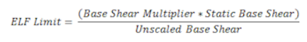
-
The I/R Limit simply takes the elastic dynamic base shear and reduces it to an inelastic base shear. This value is calculated per the I (Importance Factor) and R (Response Modification Coefficient). You can edit these values in the Seismic tab of Model Settings.
- The Controlling Limit is the governing (larger) value of the ELF limit and I/R limit.
It is important to note that these values are transferred automatically from the RISA-3D analysis only when RSA results are transferred. The program calculated scaling factor cannot be modified from within RISAFoundation. If you would like to update this value you will need to transfer back to RISA-3D to do so.
User Input
If you would like to use a different scaling factor you can select the User Input option and manually enter a custom value to override the program calculated value.
Apply Check box
The Apply SF to current RSA Load Combinations check box will apply the SF scale factors to all load combinations that currently reference response spectra results.